

I-Beam Climbing Robot
Mechanical Systems Design Final Project
Design Objective
For this project, we were tasked to design and build a small robot to climb an I-beam as fast as possible while carrying a payload at a specified distance and orientation to the beam. We were allowed to use a small DC motor, and some small shafts and bearings. All other pieces would have to be 3D printed out of PLA. Our team used FBD analysis, motor analysis, concept generation, and empirical testing to create a mass-efficient design of assemblies of custom parts.
Specifications and Constraints
Design a robot to climb up an I-beam as fast as possible while carrying an offset payload.
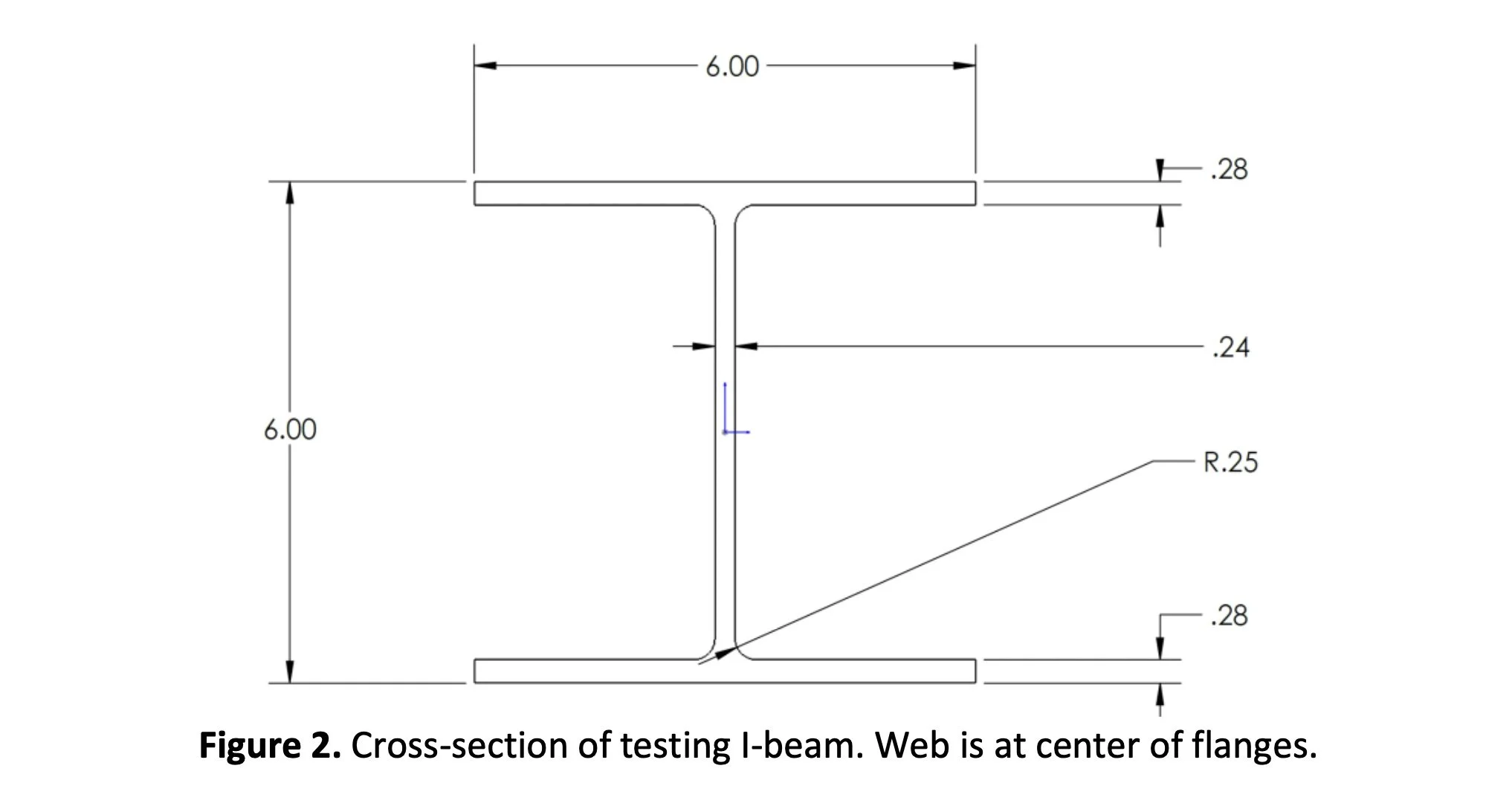
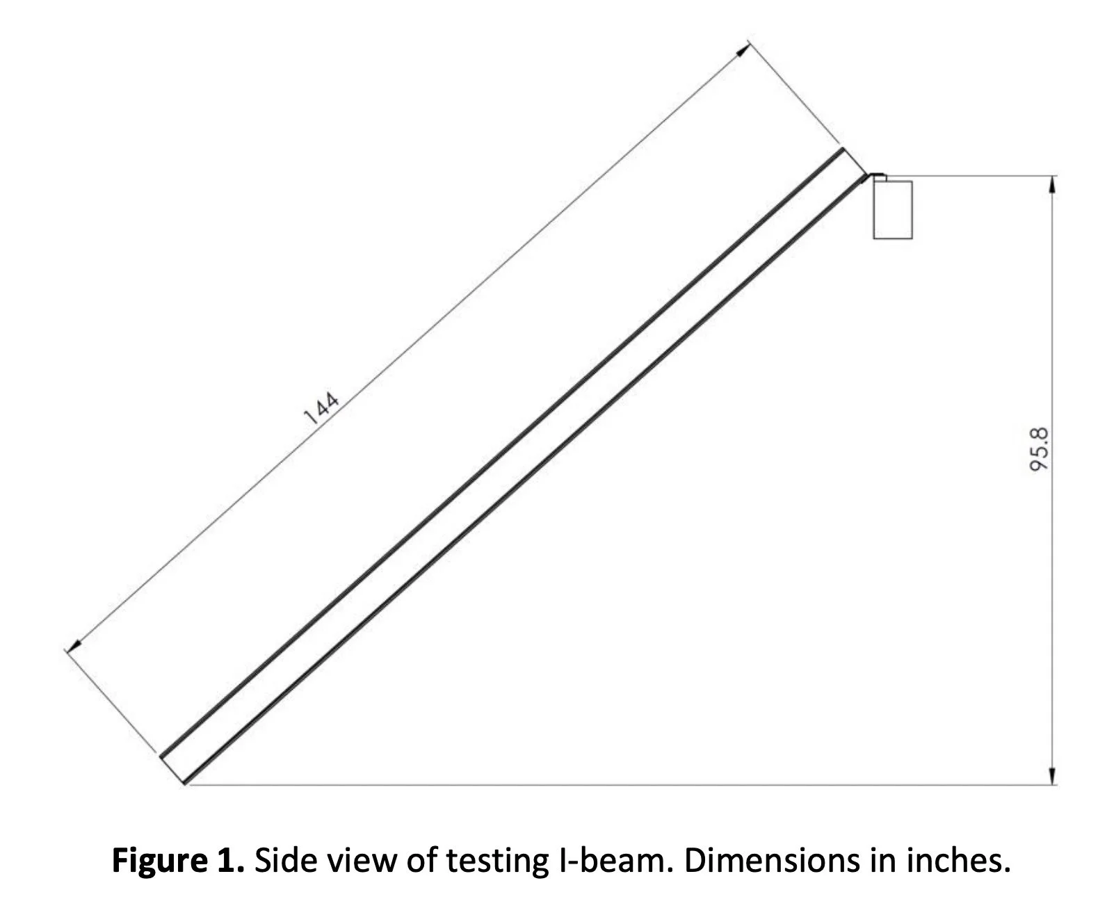
The I-beam will have the length and orientation depicted in Figure 1, and cross-section depicted in Figure 2.
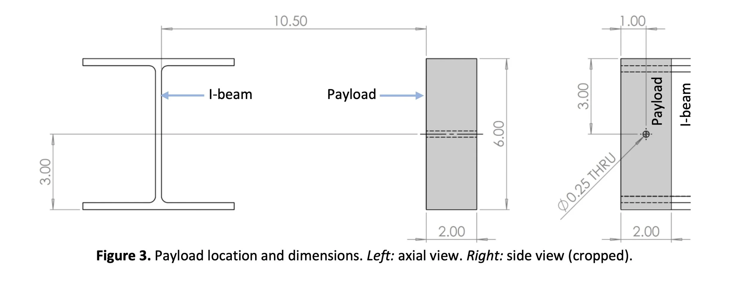
The 1 kg payload will be made of aluminum, with dimensions as depicted in Figure 3. It must be carried with position and orientation relative to the I-beam as depicted.
The robot and the payload must move in unison; the robot cannot remain stationary while the payload is lifted or vice versa; no portion of the robot can remain stationary while the rest moves.
Climbing speed will be defined by the time required for the robot to traverse 1 m along the length of the I-beam. You will design your robot to minimize the time required for the robot to go the distance.
Transmission Analysis
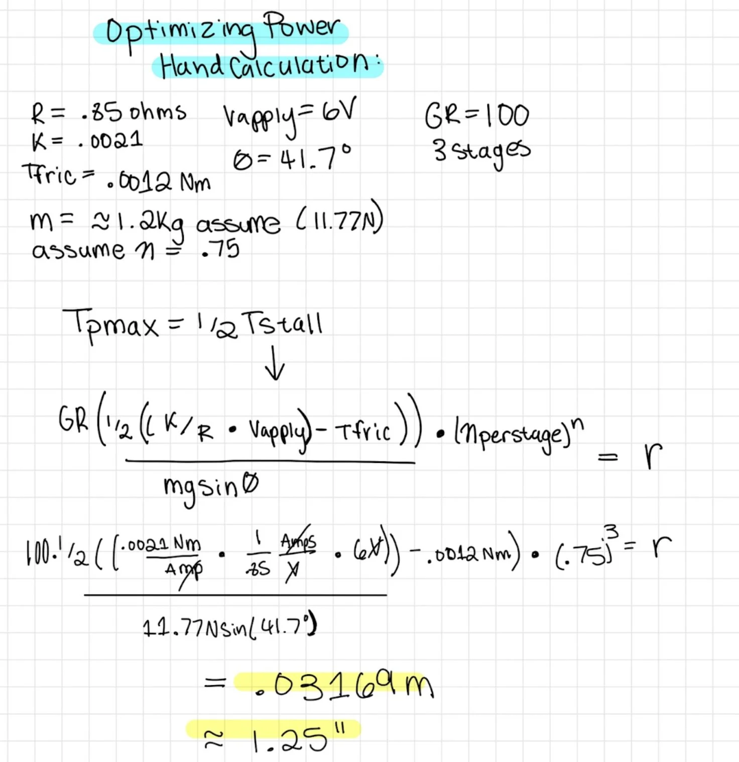
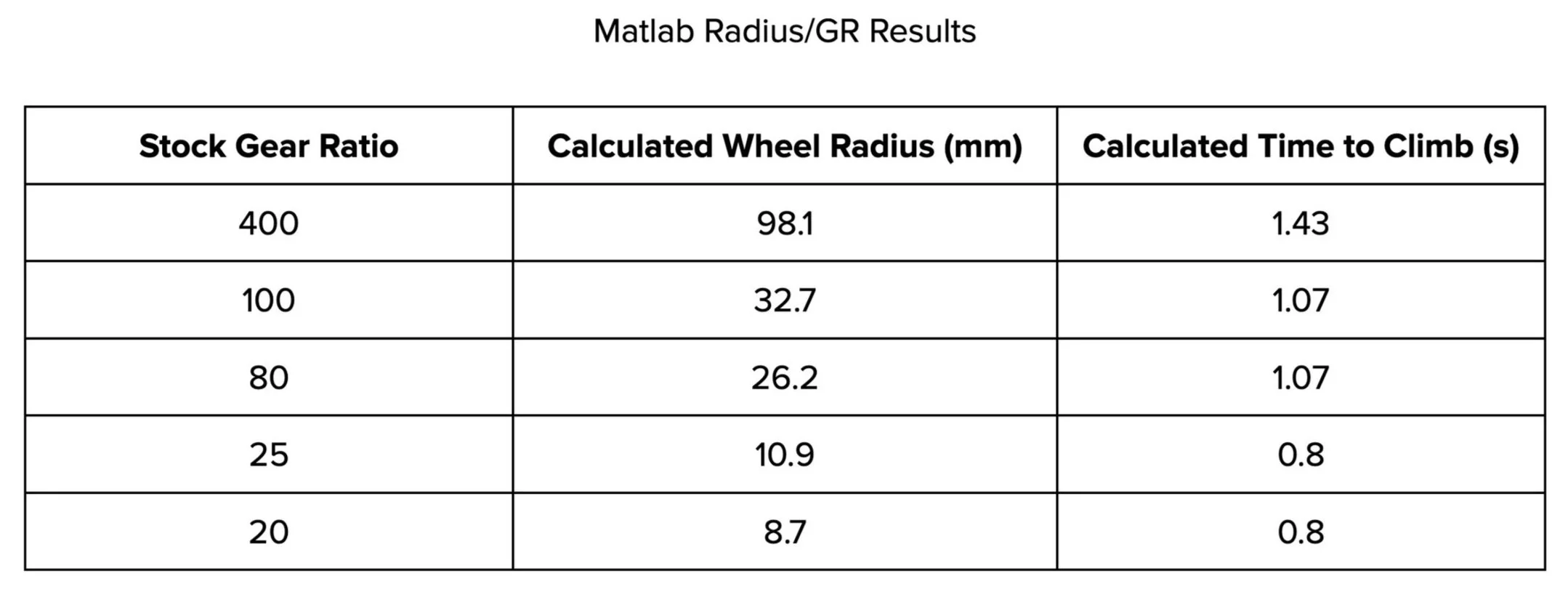
In order to decrease the time to climb, we want max power, so the torque at max power was calculated. To calculate this torque, an equation was derived that is equal to ½ the stall torque. This equation was calculated by hand and incorporated into a Matlab script to estimate various combinations of the wheel radius and stock gear ratios that would allow the robot to climb the beam at max power.
In order to maximize power, the maximum voltage would be used, which was capped at 6 Volts for this project. After calculation, the selected combination of parameters was a wheel radius of 32.7 mm and a gear ratio of 100:1. This combination was selected using a 3-stage gearbox, which was calculated to be faster than having a 4 stage gearbox while still providing sufficient torque. Additionally, the calculated combination gave the fastest time to climb, while keeping a wheel radius that was a reasonable size compared to the physical size of the motor. This comparison was considered in order to have the wheel in direct transmission, and prevent efficiency loss through more gears.
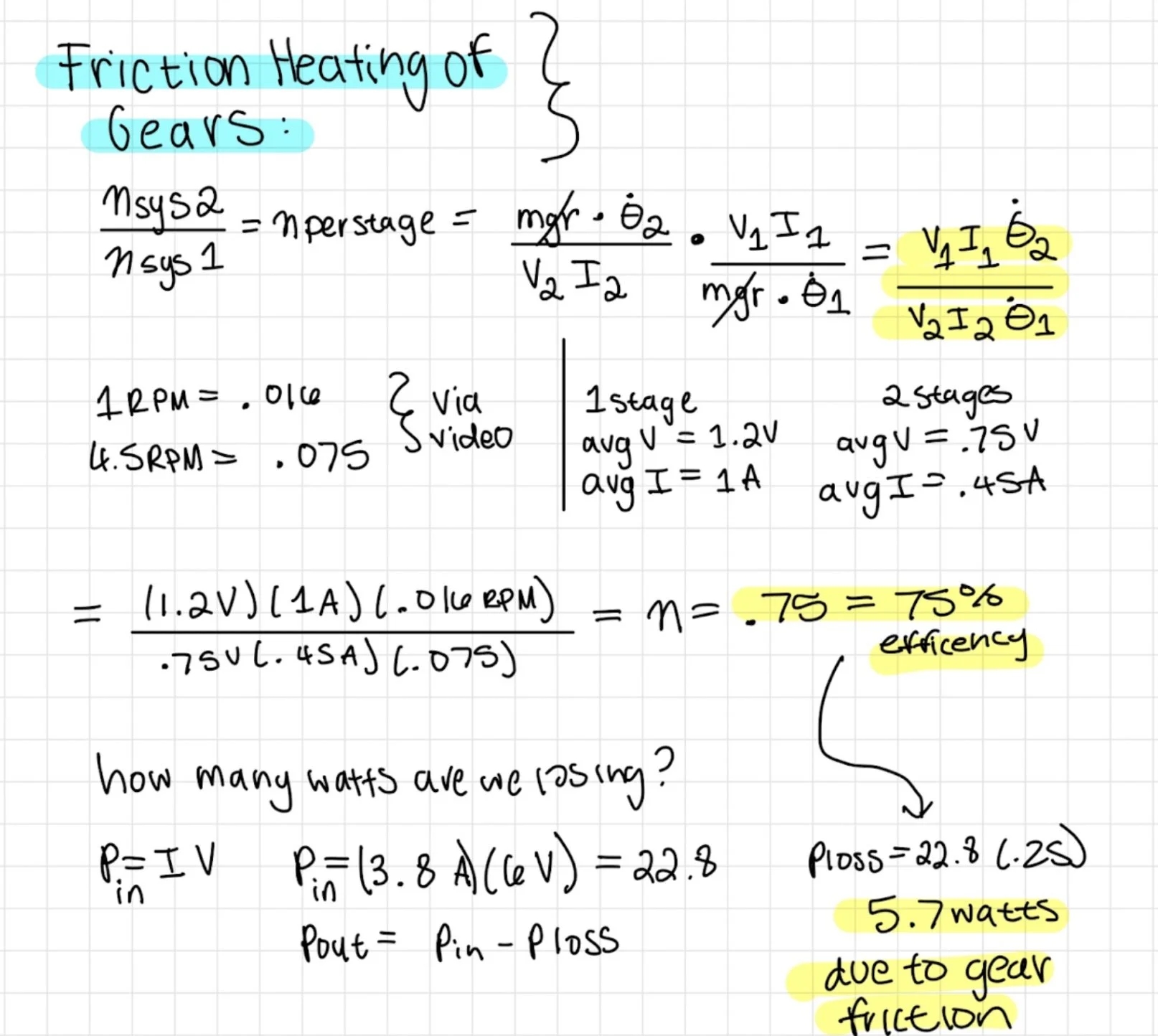
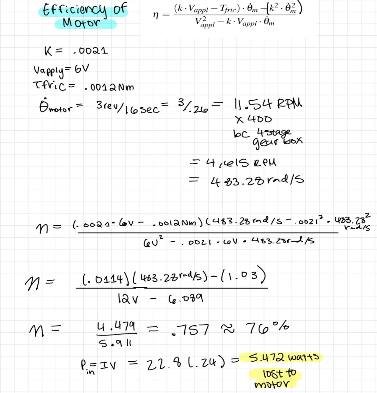
Efficiency of the motor was calculated using constants that were calculated through taking experimental measurements using the motor at 0 and max stall. This resulted in a calculated motor efficiency of 76 percent. Additionally, power loss was calculated considering friction heating of the gears, as well as bearing and wheel deformation, however these were calculated to be 0.005 Watts, and were determined to be negligible. A loss of 5.7 Watts was calculated to be due to gear friction.
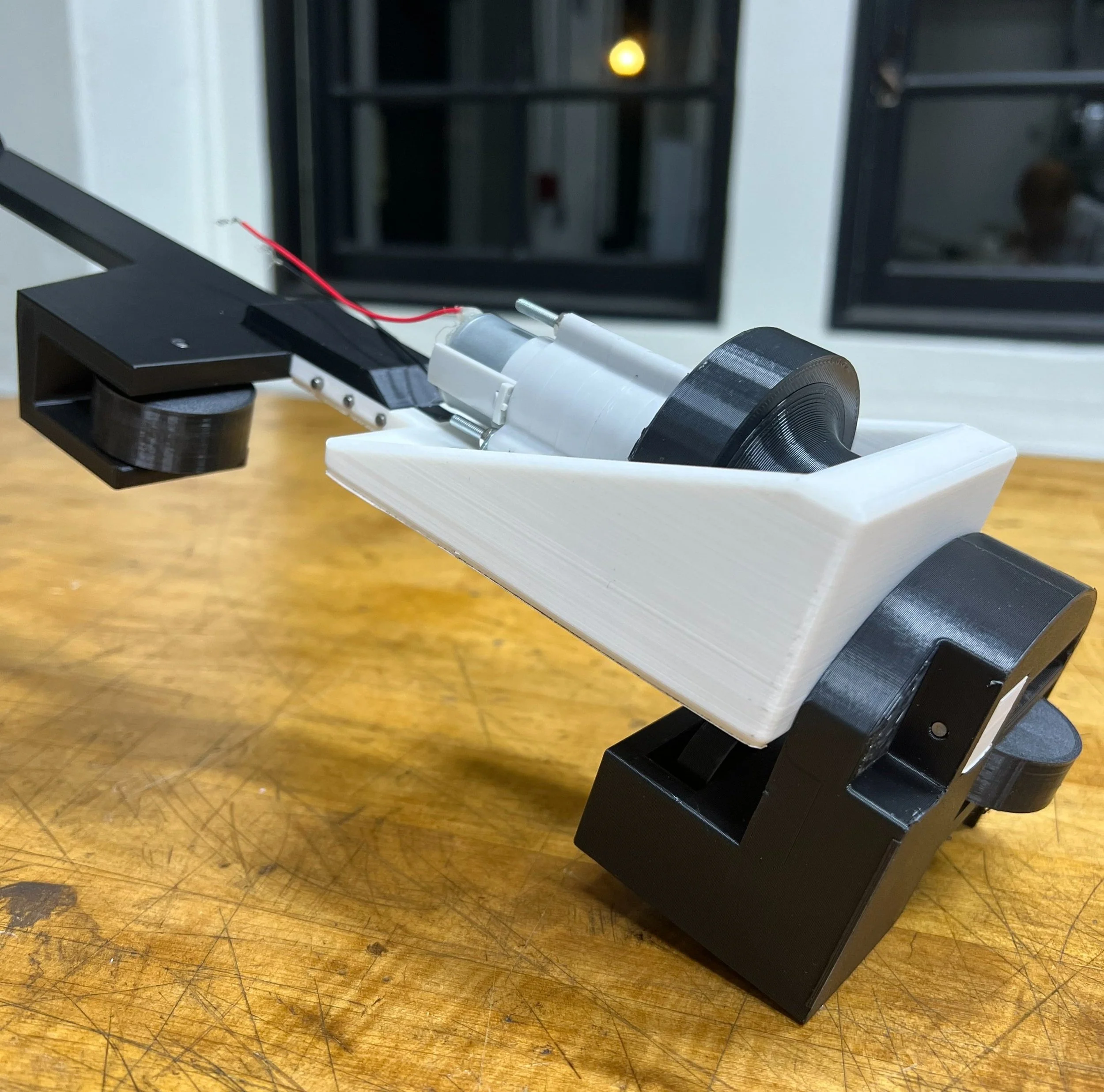
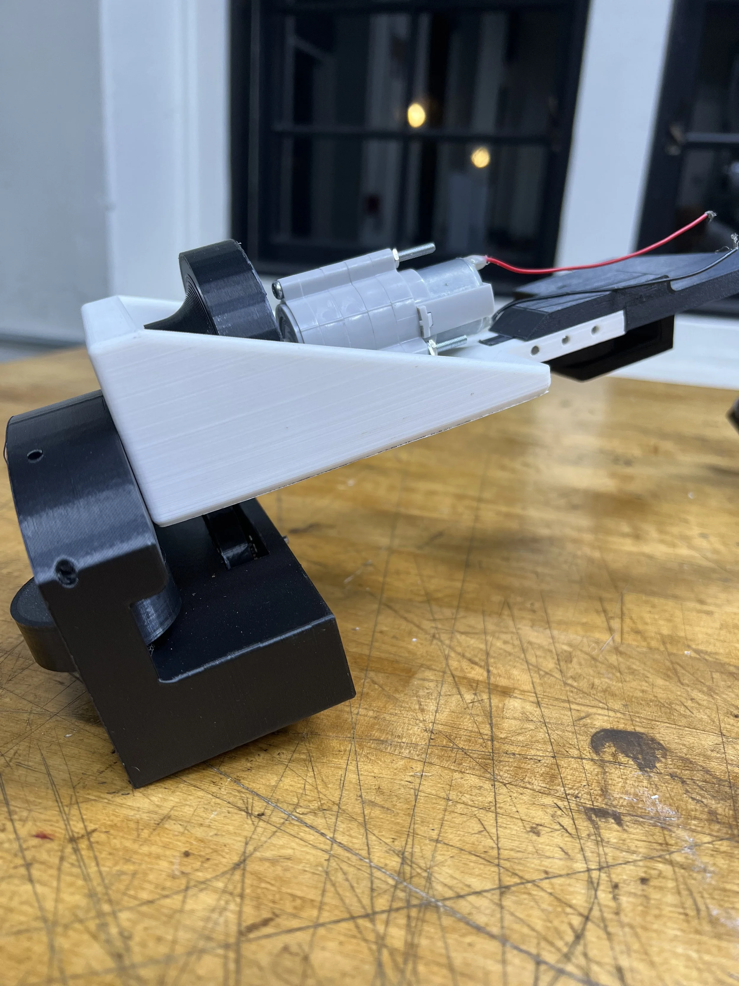
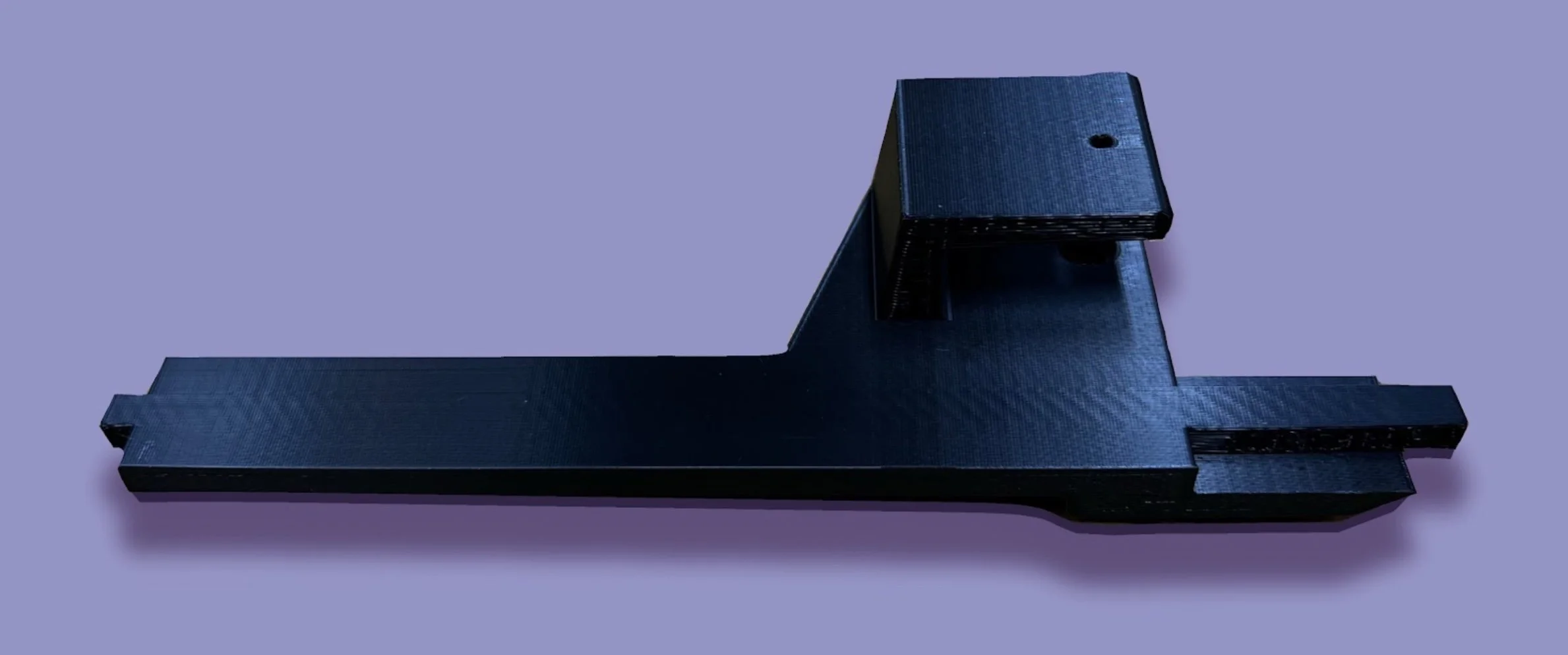
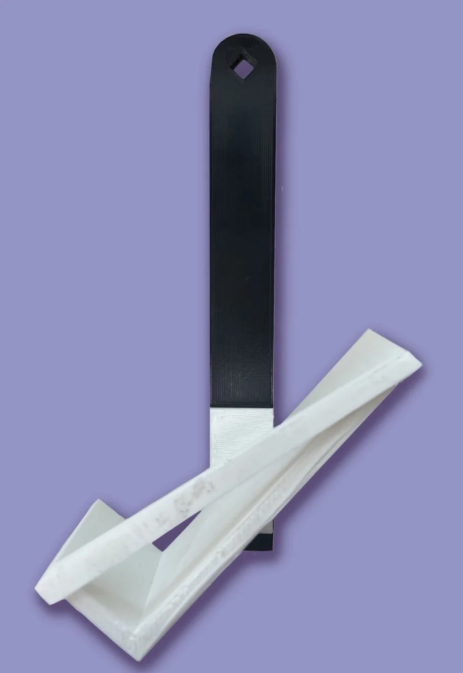
Chassis Design
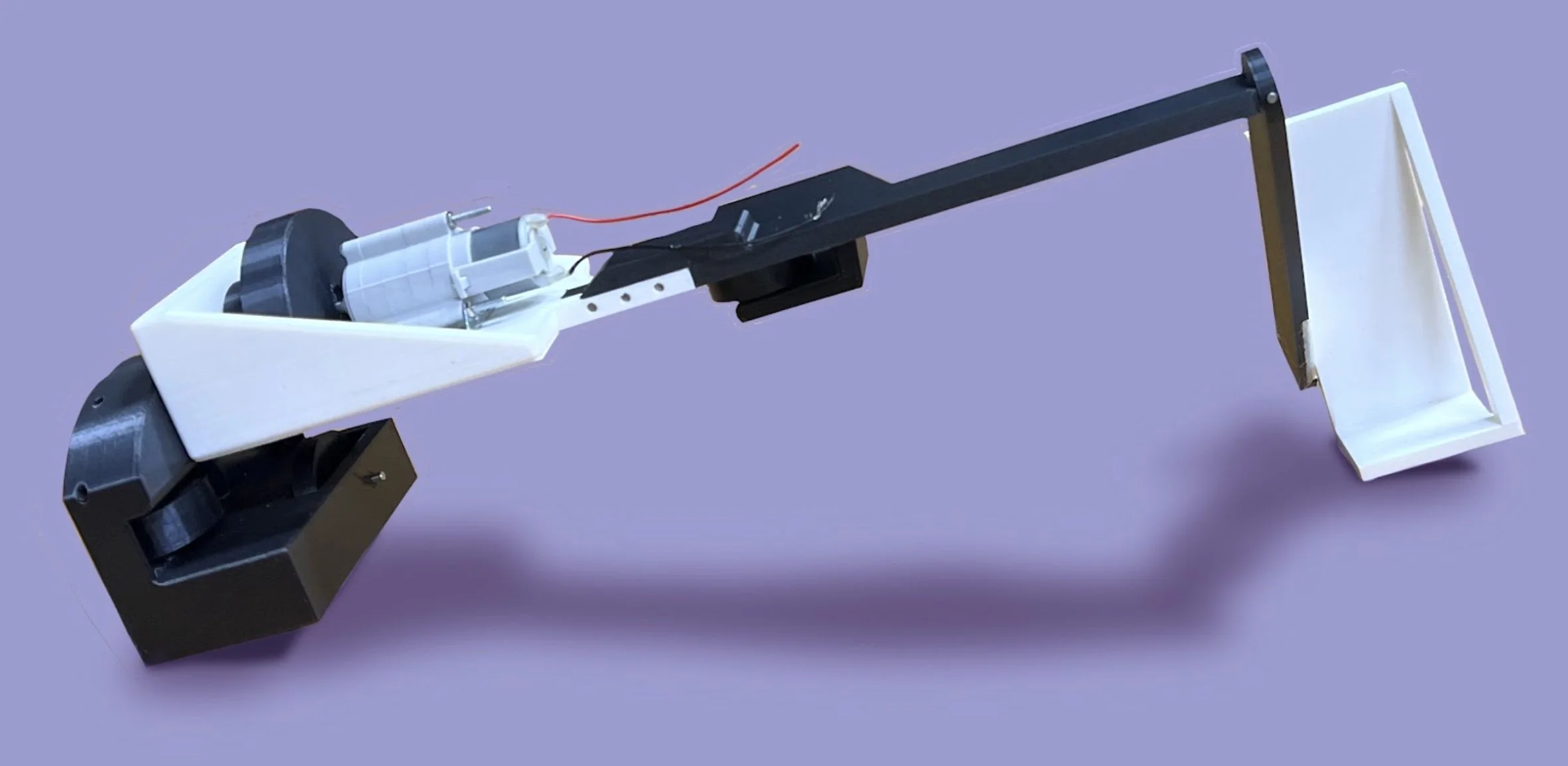
The robot utilizes a simple design of a chassis, one driving wheel and three passive wheels to constrain the robot around the beam, as well as a horizontal and vertical beam to hold the payload in the specified orientation.
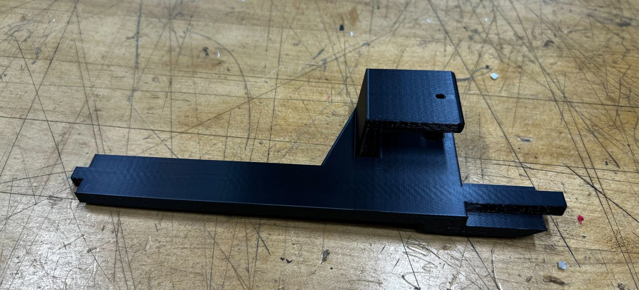
Stress analysis and FEA were used to determine the dimensions of the top and side beam to prevent breaking, reduce deflection, and increase mass efficiency. To reduce beam deflection, the thickness was increased above and around the connection between the top beam and the chassis. The side beam was designed to hang vertically to the ground to eliminate torsion on the connection point between the top and side beam, with a “cradle” attachment to keep the payload in the specified orientation. The cradle was positioned outside of the vertical beam to reduce the maximum applied moment. Fixed connections between the side beam, top beam, chassis, and side housing were created using square pegs and pin connections in order to constrain against all degrees of freedom.
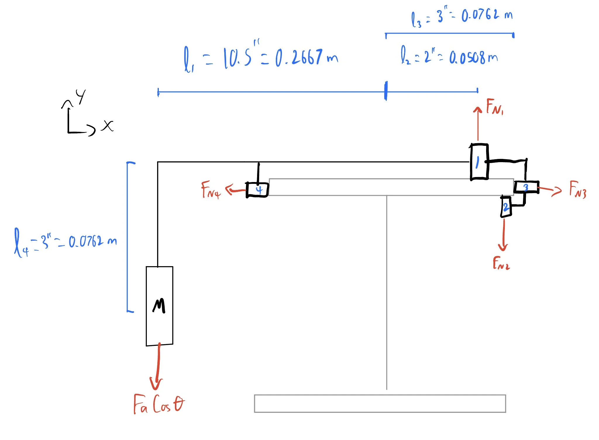
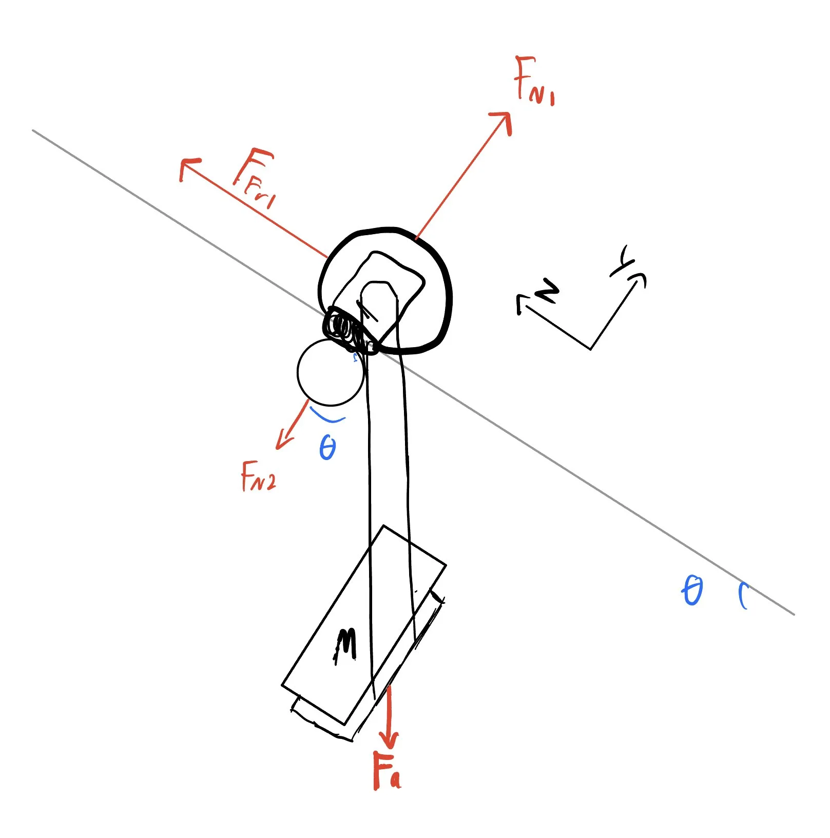
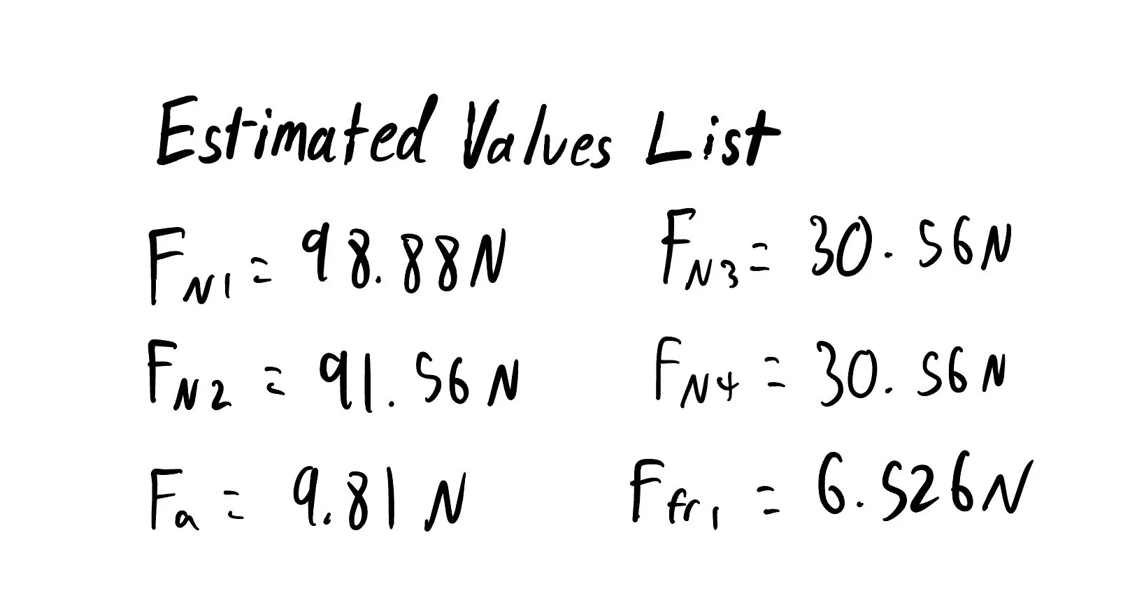
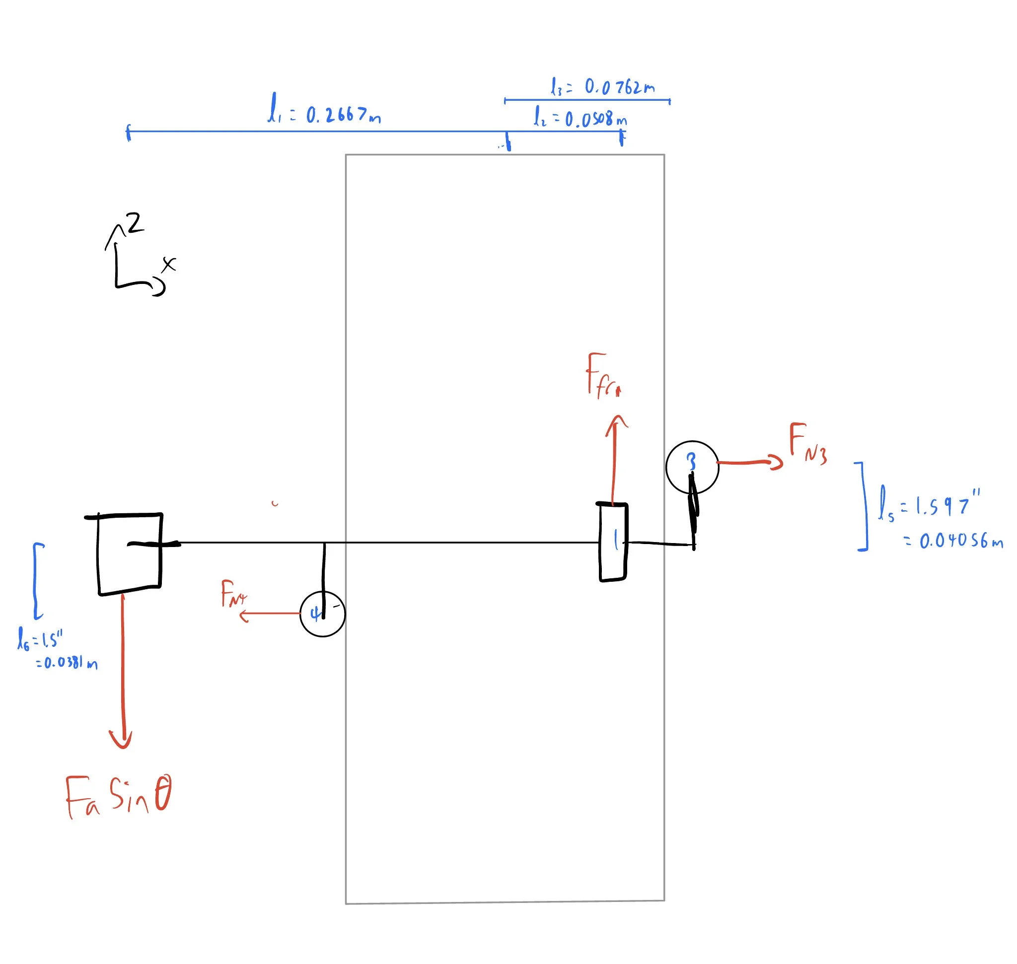
The normal force on the driving wheel was the most critical aspect of the design, as material constraints required us to sustain the coefficient of friction of 0.1. This variable was determined using FBDs, and maximized by increasing the length of the lever arm from the payload to the driving wheel. Solving the FBDs gave us a minimum value of 98.88 N for this value. Four wheels were used to counteract the moment on the driving wheel created by the payload in two planes and achieve static equilibrium. This was achieved by including the driving wheel on top of the I-Beam, the bottom wheel under the lip, and two side wheels offset from the horizontal axis of the robot to act as constraints.
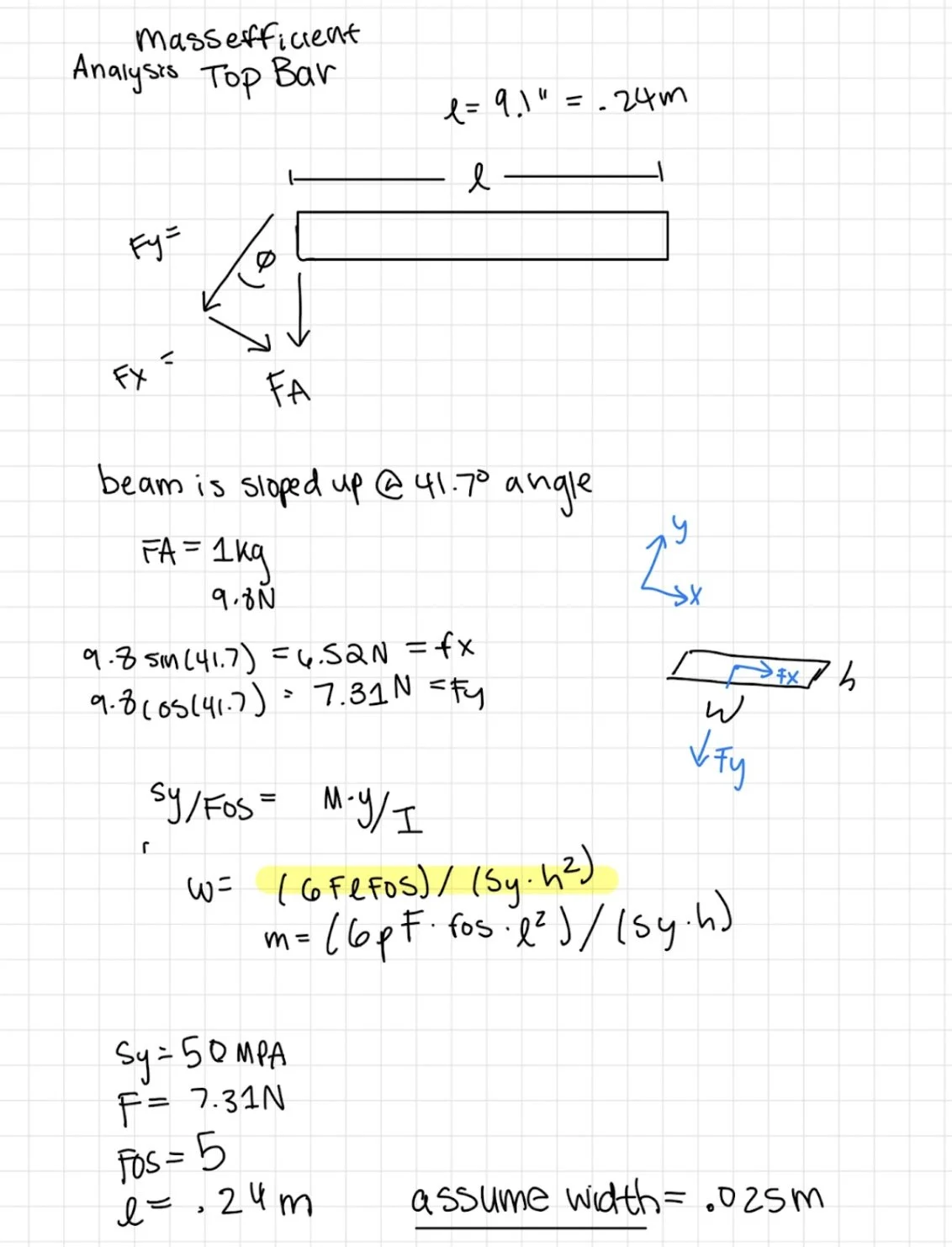
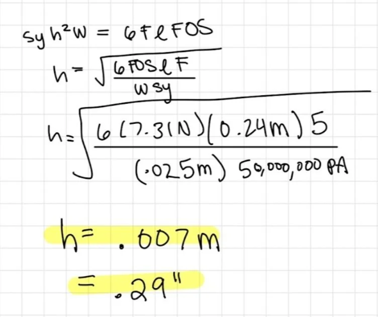
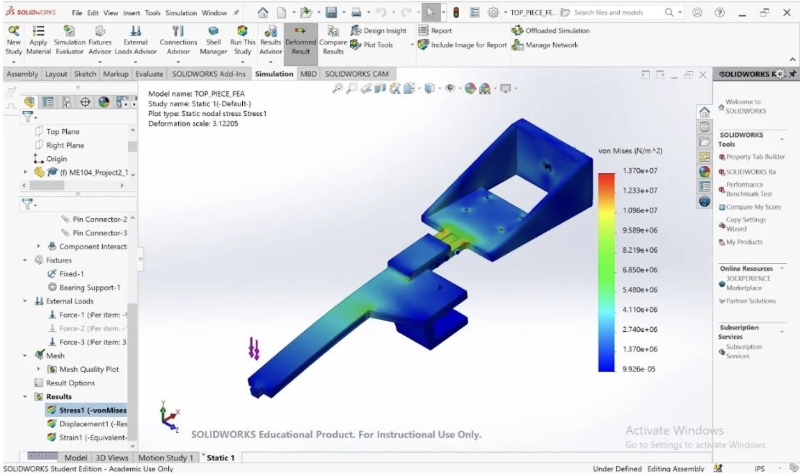
Top Bar Analysis
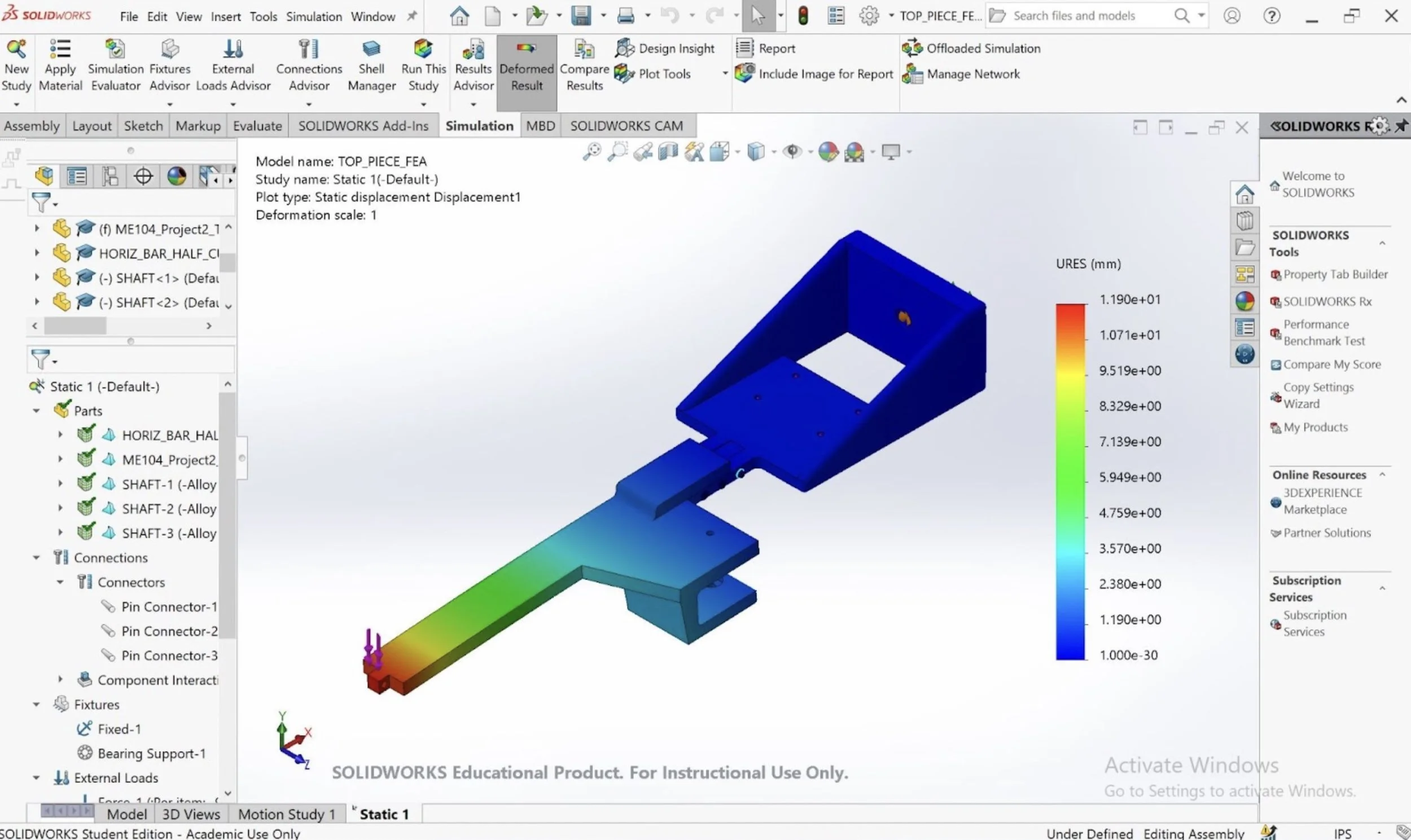
The top bar of the robot is fixed on one end and supports the payload on the other, and can thus be analyzed as a beam. The max deflection is the distance until the top bar touches the I-beam, so deflection analysis was done using a safety factor of 5 showed us that the top bar thickness must be 7 mm. The supported end of the top bar has three pin connections, fixing it rigidly to the motor housing. The FEA illustrates that the pin connections at this end of the bar are the most stressed area of the component. In order to prevent deflection here, this part of the bar has a thickness twice the size of the rest of the component. The free end of the bar has a square peg and shaft that goes through the sidebar to prohibit the payload from swinging or falling.
FEA considers the reactions of the chassis and the horizontal bar fixed together, to account for the forces acting on the part via the driving wheel. The load acting on the shaft and bearing connecting the driving wheel to the chassis is half of the normal force acting on the driving wheel, or 49.44N, and each of the four holes that constrain the motor to the chassis bears an ⅛ of the normal force, or 12.36N. There is also a 9.81N load acting on the free end of the top bar, simulating the weight of the payload.
The displacement analysis of the top bar and the chassis demonstrates deflection at the end of the shaft close to the pin connection between the top and side bars. The thickness of 7mm is set to accommodate for the deflection of the top bar. With this design parameter, the top bar is expected to only deflect 1 cm at the greatest point of displacement.
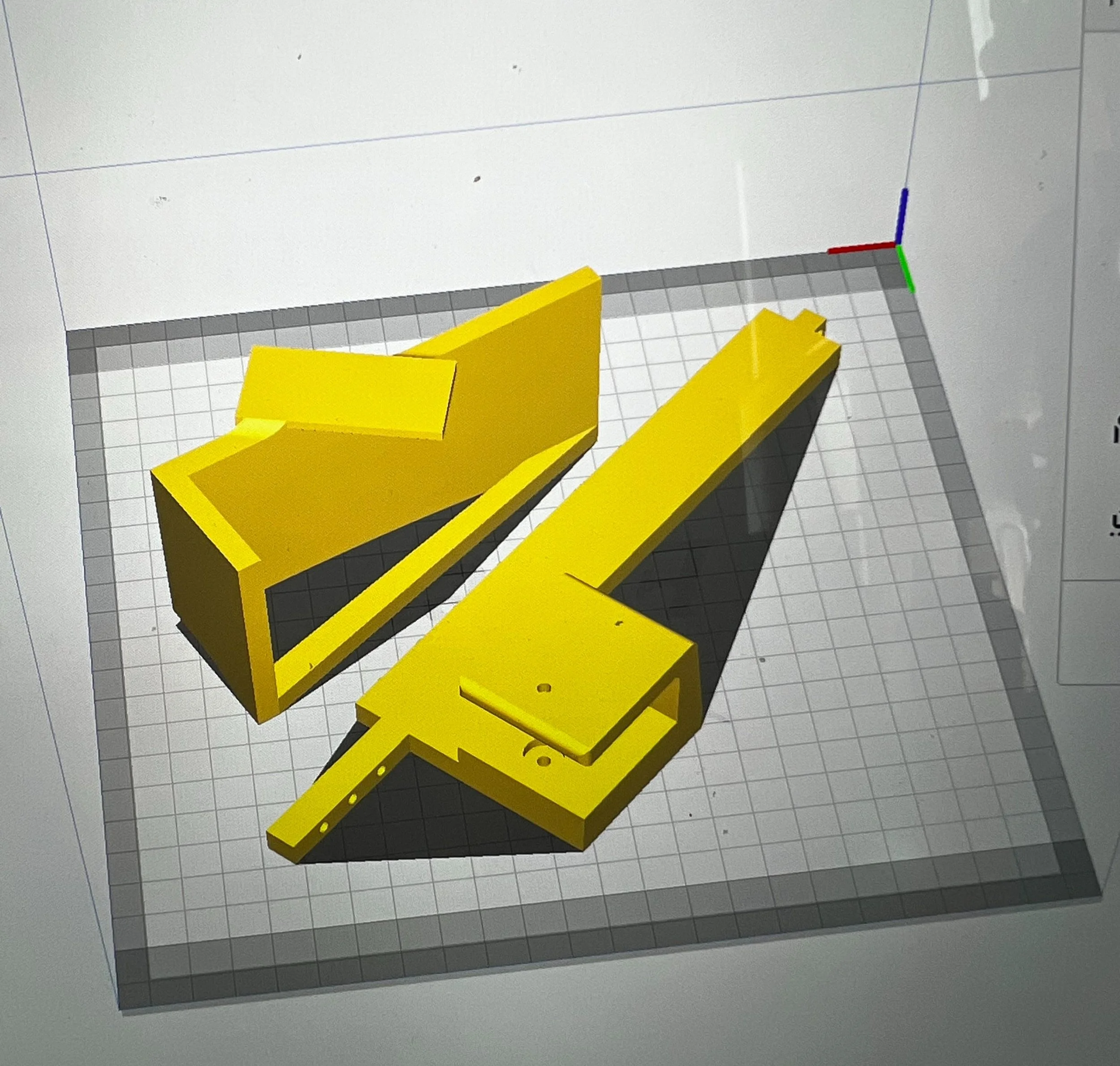
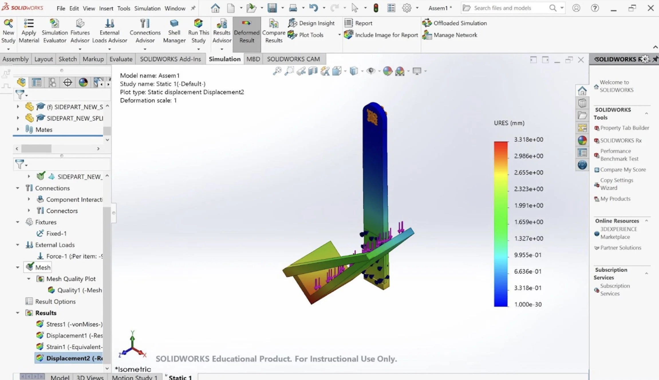
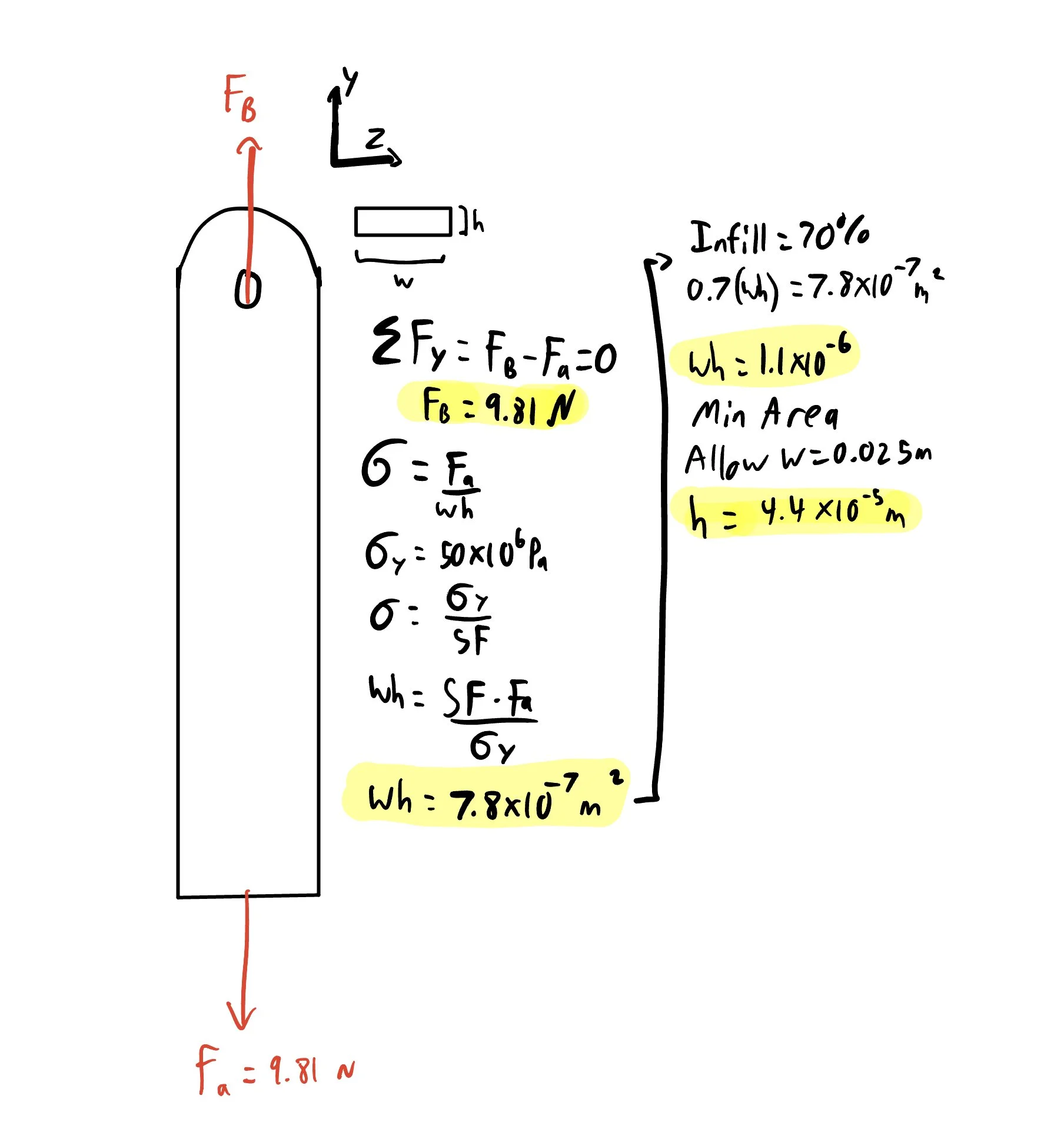
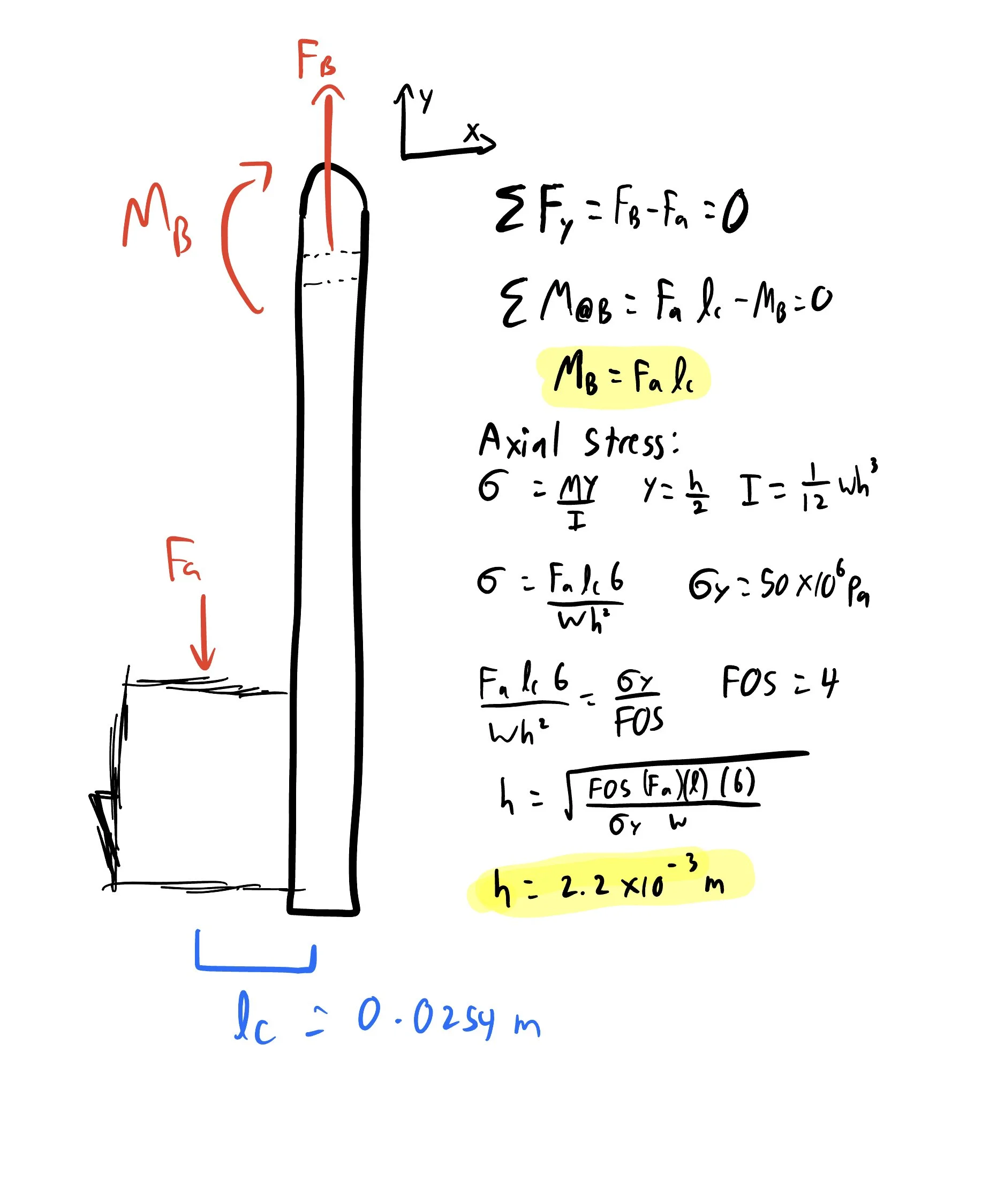
Side Bar Analysis
The sidebar was designed as two pieces, fixed together using adhesives: the vertical bar that implements a square slot to conjoin with the top bar, and the 41.7° angled cradle to hold the payload. The slot for the top bar accounts for a square peg and a pin connection, so that the sidebar could be positioned vertically, to reduce torsion on the connection point and to reduce swinging. This choice eliminated torsion and resulting stress and deflection, too much of which would result in interference between the top bar and the I-beam, reducing the normal force on the driving wheel. To comply with requirements for the position of the payload, a “cradle” attachment physically constrains the payload at the proper angle. Holding the cradle on the outside of the vertical bar decreases the max moment, and results in a shortened top bar. To follow the existing geometry of the top bar, the width of the sidebar is selected to be 0.025m and the thickness of the bar is then calculated to be 2.2 mm with a factor of safety of 4.
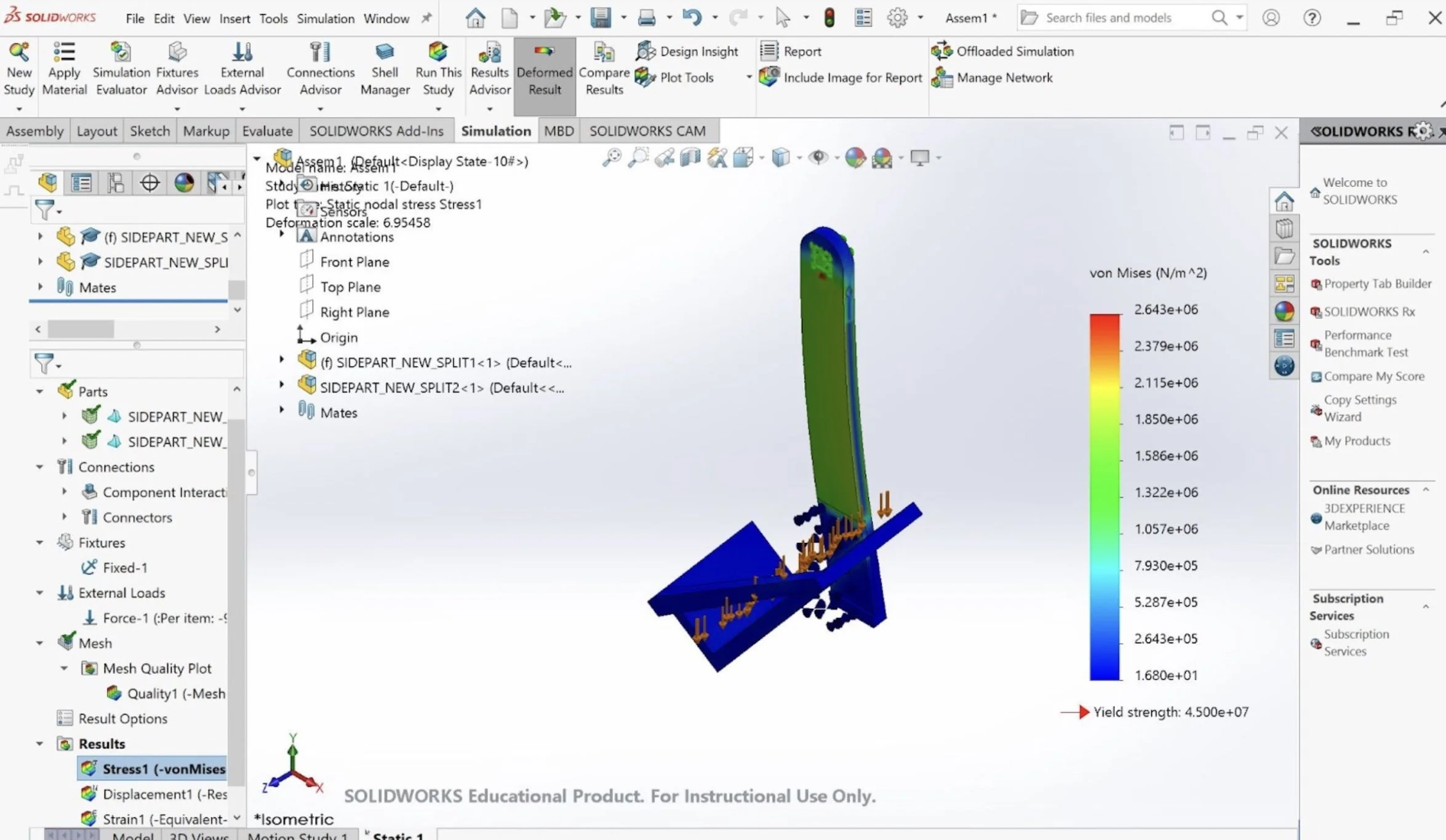
An FEA study was conducted on the part by fixing the square peg as it is restricted in all degrees of freedom. A force of 9.81 Newtons was vertically applied on the surface of the cradle. Our FEA results show that our part is unlikely to break during the applied load, and will slightly deform towards the I-beam. The FEA results show the highest stress concentrations are around 90° angle of the cradle. However, even the highest stresses of the part are well under the yield stress of PLA. This is by design, as a high safety factor of four was chosen to ensure that the part does not break if the mass is bouncing or is experiencing other complications.
Allowing the bar to remain vertical to the ground, reduces the deflection and stress, resulting in a more efficient part. The FEA supports this idea by showing the minimal stress experienced by the sidebar. However, the sharp angle in the cradle is experiencing a higher stress, so a crossbar was added and the thickness of the cradle was increased such that the stress does not exceed beyond 12.5 MPa.
Skills Learned
-
This course taught me how to use material and force constraints to isolate geometric variables to reduce the volume and create an efficient design. Learning how to distribute loads efficiently across the structure helped me to prevent excessive stress, increase leverage, and reduce excessive mass.
-
This project helped me gain proficiency in FEA simulations to know how to set up models, define materials, and interpret results. Knowing how to apply boundary conditions, loads, and constraints helped us confirm design choices and optimize parts.
-
This project how to consider the torque and speed requirements of DC motors based performance requirements. Learning about the characteristics of DC motors, including torque-speed curves, power ratings, and efficiency, helped me to make informed and effective decisions during the design process.
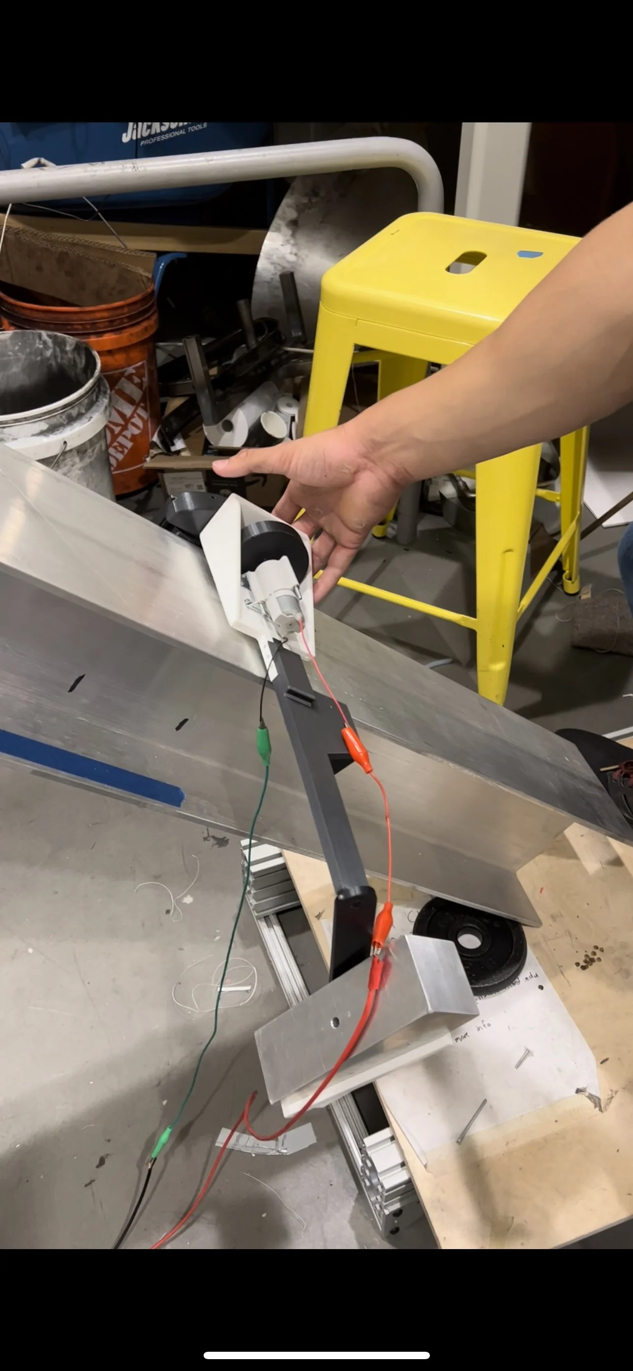
Functionality Verification
The Final Results! Our bot was able to climb the specified distance in only 3.93 seconds!